Today I decided to do something different. Instead of the usual machine learning content, I decided to write about LoRa, a long-range, low-power wireless communication technology, which I took a look at the last couple of days.
This article will give you a basic overview of what LoRa is and what it can be used for. Furthermore, I'll show you how to do point-to-point communication using two ESP32 and two RFM95 LoRa modules. In another article, I plan to cover how to use LoRaWAN with The Things Network. If you want to see more engineering articles like this, be sure to let me know.
What is LoRa?
LoRa is a spread spectrum modulation technique derived from chirp spread spectrum (CSS) technology. LoRa allows for long-range, low-power wireless communication, often applied in IoT (Internet of Things) applications.
Different LoRa Frequencies
LoRa uses license-free radio frequency bands. The most widely used frequencies are:
- 868MHz in Europe
- 915MHz in Australia and North America
- 923MHz in Asia
LoRa Applications
Because of its huge range and low power consumption LoRa can be widely applied in applications like:
- Internet of Things (IoT)
- Smart Home
LoRa with ESP32 (Point to Point Communication)
Getting started with Lora is pretty straightforward. You only need two LoRa modules, like an RFM95, and two microcontrollers (ESP32 for this guide).
One of the two will play the sender. The other one will receive the messages and will react accordingly.
Preparing the Arduino IDE
Before you can get started working with LoRa, you need to install all the necessary add-ons needed to get the ESP32 and LoRa working in the Arduino IDE:
ESP32 support for the Arduino IDE
If you haven't already, you'll need to install an add-on that allows you to program an ESP32 using the Arduino IDE.
Guide: Installing the ESP32 Board in Arduino IDE (Windows, Mac OS X, Linux)
Installing the LoRa Library
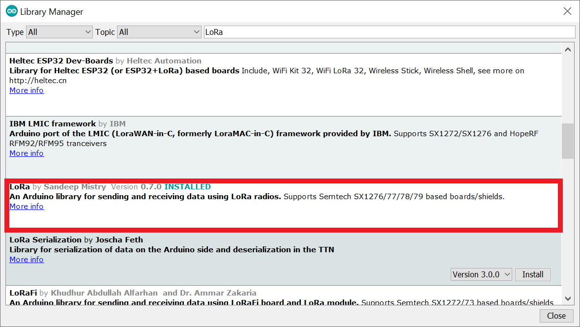
Several libraries are available that allow you to use LoRa with the ESP. For this guide, we'll use the arduino-LoRa library created by sandeepmistry.
Open the Arduino IDE, go to Sketch > Include Library > Manage Libraries, and search for LoRa. Scroll down until you find the right library and click install.
Wiring RFM95 and ESP32
The RFM95 communicates with the microcontroller over SPI. So you can connect the RFM95 to the default SPI pins of the ESP32, as shown in the following image:
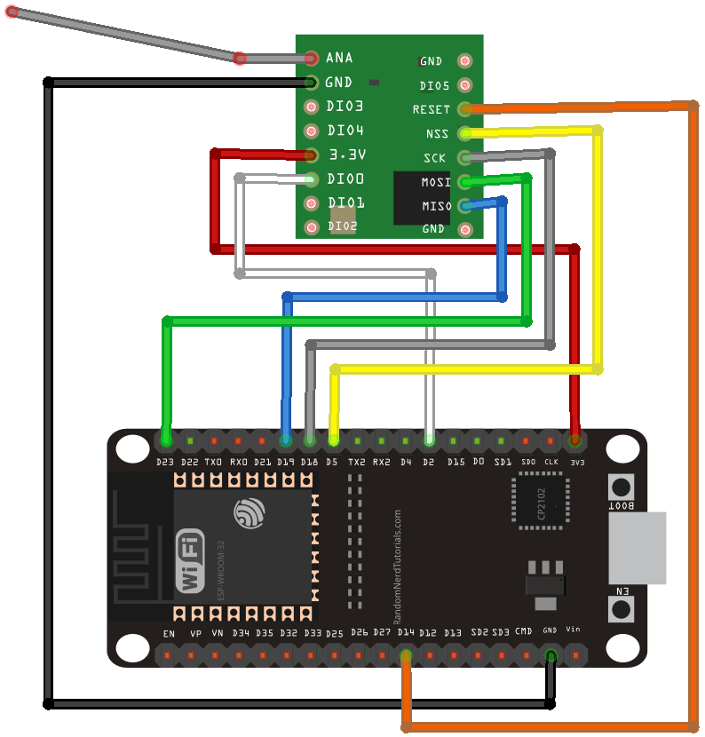
Note: Of the 3 GND Pins, only one needs to be connected.
Important: Don't forget to connect an antenna to the ANT pin.
LoRa Sender Example Sketch
The LoRa library has a sender and receiver example script, which you can open by going to File > Examples > LoRa > LoRaSender. However, you will have to make a few little changes to get it to work:
#include <SPI.h>
#include <LoRa.h>

#define ss 5
#define rst 14
#define dio0 2

int counter = 0;

void setup() {
  Serial.begin(9600);
  while (!Serial);

  Serial.println("LoRa Sender");

  LoRa.setPins(ss, rst, dio0);

  if (!LoRa.begin(866E6)) {
    Serial.println("Starting LoRa failed!");
    while (1);
  }
}

void loop() {
  Serial.print("Sending packet: ");
  Serial.println(counter);

  // send packet
  LoRa.beginPacket();
  LoRa.print("hello ");
  LoRa.print(counter);
  LoRa.endPacket();

  counter++;

  delay(5000);
}
Let's break this down piece by piece:
It starts by including the needed libraries.
#include <SPI.h>
#include <LoRa.h>
Then, it defines the pins used by the LoRa module. If you've followed the schematic above, you should have the following pins:
#define ss 5
#define rst 14
#define dio0 2
You can set the pins inside the setup method by calling the .setPins method. Afterward, you can initialize the LoRa module by calling Lora.begin(frequency), passing it the right frequency for your location.
With the initialization done, you can send data using the following code:
LoRa.beginPacket();
LoRa.print("hello ");
LoRa.print(counter);
LoRa.endPacket();
LoRa Receiver Example Sketch
The receiver sketch is very similar to the sender sketch. The only differences are in the loop method, where instead of sending data, the script is receiving data.
#include <SPI.h>
#include <LoRa.h>

#define ss 5
#define rst 14
#define dio0 2

void setup() {
  Serial.begin(9600);
  while (!Serial);

  Serial.println("LoRa Receiver");

  LoRa.setPins(ss, rst, dio0);

  if (!LoRa.begin(866E6)) {
    Serial.println("Starting LoRa failed!");
    while (1);
  }
}

void loop() {
  // try to parse packet
  int packetSize = LoRa.parsePacket();
  if (packetSize) {
    // received a packet
    Serial.print("Received packet '");

    // read packet
    while (LoRa.available()) {
      Serial.print((char)LoRa.read());
    }

    // print RSSI of packet
    Serial.print("' with RSSI ");
    Serial.println(LoRa.packetRssi());
  }
}
Testing the Scripts
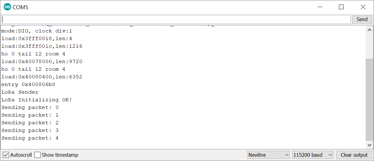
To test if everything is working correctly, you need to connect both ESPs to a PC and open the Serial Monitor.
The Lora Sender script should have the following output:
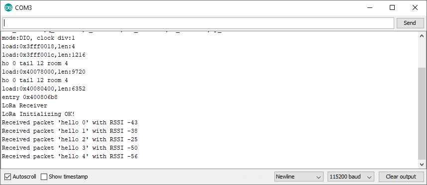
The output of the receiver scripts:
Conclusion
LoRa is a spread spectrum modulation technique derived from chirp spread spectrum (CSS) technology. Because of its long-range and low power consumption, it's often applied in IoT applications.
In this article, you learned how to use LoRa to create a point-to-point communication between two ESP32 microcontrollers. In an upcoming article, I'll show you how to create a LoRa network using LoRaWAN.
That's all from this article. If you have any questions or want to chat with me, feel free to contact me via EMAIL or social media.