Testing autonomous systems in simulation before deploying them on real hardware is essential — especially when working with multiple vehicles that need to coordinate. Over the past months, I’ve been building multiagent simulation frameworks for both PX4 and ArduPilot, targeting drones, ground robots, and fixed-wing aircraft in Gazebo. The goal was to make it easy to spawn multiple vehicles with configurable sensors, proper ROS 2 namespacing, and support for feeding in external odometry — all the things you need for developing SLAM, path planning, and multi-robot coordination algorithms.
This post gives an overview of both frameworks and how to get started with each.
Why Multiagent Simulation Matters
When developing multi-robot systems — whether it’s a swarm of drones for search and rescue or a fleet of ground robots for warehouse logistics — you need a simulation environment that can:
- Spawn an arbitrary number of vehicles with independent control
- Keep each vehicle’s topics, services, and transforms properly namespaced to avoid conflicts
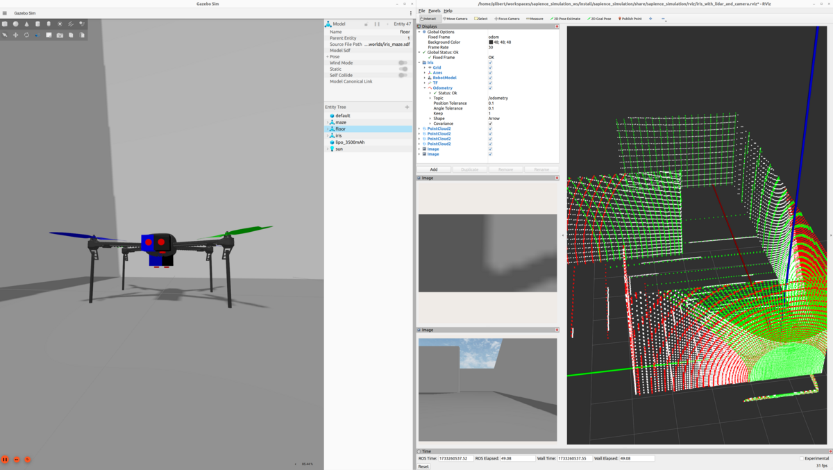
- Support different sensor configurations (LiDAR, cameras, depth sensors) per vehicle
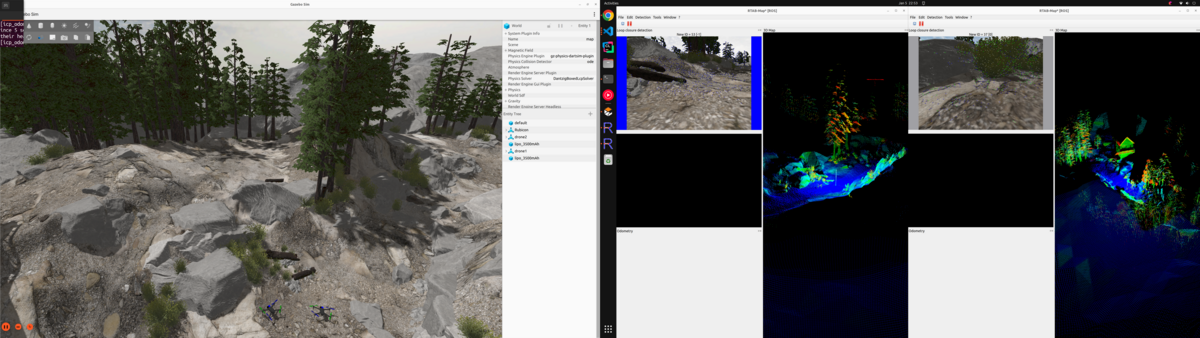
- Allow external odometry input for testing SLAM and visual-inertial odometry pipelines
- Run on standard ROS 2 tooling so your code transfers to real hardware with minimal changes
Both the PX4 and ArduPilot frameworks I’ve developed address these requirements, but they take different approaches due to the architectural differences between the two autopilot stacks.
PX4 Multiagent Simulation

The PX4-Multiagent-Simulation repository provides a ROS 2 / Gazebo simulation environment for multiple PX4-powered vehicles. Drone models are defined using xacro files, making it easy to add or remove sensors like LiDARs, cameras, and depth sensors.
Setup
- Install PX4 Autopilot following the ROS 2 User Guide
- Clone the repository:
git clone --recurse-submodules https://github.com/TannerGilbert/PX4-Multiagent-Simulation.git
- Add the custom airframe to PX4:
cp src/multiagent_simulation/config/22000_gz_x500_with_lidar_and_camera <PX4-Autopilot-path>/ROMFS/px4fmu_common/init.d-posix/airframes/
- Build the workspace:
cd PX4-Multiagent-Simulation
rosdep install --from-paths src --ignore-src -r -y
colcon build --symlink-install --cmake-args -DCMAKE_BUILD_TYPE=Release
Running the Simulation
source install/setup.bash
ros2 launch multiagent_simulation multiagent_simulation.launch.py
You can specify different worlds:
ros2 launch multiagent_simulation multiagent_simulation.launch.py world_file:=rubico.sdf
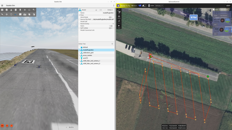
Available worlds include techhive.sdf, rubico.sdf, baylands.sdf, harmonic.sdf, and a photogrammetry-based modelflughafen world.
Namespacing in PX4
Proper namespacing is critical for multiagent systems. Without it, topic names collide and you can’t tell which sensor data belongs to which vehicle.
In the PX4 framework, each vehicle gets a namespace following the pattern px4_<i>:
- Topics:
/px4_1/fmu/out/vehicle_odometry,/px4_2/fmu/out/vehicle_odometry, etc. - MAVLink ports: Drone
iuses port14540 + i*10(incoming) and14557 + i*10(outgoing) - System IDs: Sequential starting from 1
All ROS 2 nodes — state publishers, bridges, sensor processors — are scoped to their respective namespaces, so you can run identical node configurations for each vehicle without conflicts.
Sensor Configuration with Xacro
Sensors are defined as xacro macros, making it trivial to customize each vehicle’s sensor payload:
<xacro:lidar_sensor
  name="lidar_1"
  pose="0.18 0.02 0.22 0 1.57 0"
  horizontal_fov="3.141592655"
  vertical_fov="0.785398165"
  horizontal_samples="1024"
  vertical_samples="128"
  update_rate="20" />
The xacro files are automatically converted to SDF at launch time, so you edit a clean template and get a full Gazebo model.
Passing External Odometry
For testing SLAM algorithms or visual-inertial odometry, you need to feed position estimates back to PX4. The framework includes an external_odometry_publisher node that:
- Subscribes to a ROS
nav_msgs/Odometrytopic (e.g., from your SLAM node) - Converts from ROS FLU (Front-Left-Up) to PX4’s FRD (Front-Right-Down) coordinate frame
- Publishes to
/px4_<i>/fmu/in/vehicle_visual_odometry
The coordinate frame conversion handles position, velocity, and quaternion transforms:
# FLU to FRD conversion
msg.position = [odom.pose.pose.position.x,
                -odom.pose.pose.position.y,
                -odom.pose.pose.position.z]
msg.velocity = [odom.twist.twist.linear.x,
                -odom.twist.twist.linear.y,
                -odom.twist.twist.linear.z]
For more details on PX4’s visual inertial odometry interface, see the PX4 VIO documentation.
ArduPilot Multiagent Simulation
The Ardupilot_Multiagent_Simulation repository provides the equivalent setup for ArduPilot. It builds on the official ardupilot_gz package and extends it with proper multiagent support, sensor configurability, and external odometry integration.
Setup
- Install ROS 2 and ArduPilot following the ROS 2 with SITL in Gazebo documentation
- Clone and build:
git clone https://github.com/aau-cns/Ardupilot_Multiagent_Simulation.git
cd Ardupilot_Multiagent_Simulation
rosdep install --from-paths src --ignore-src -r -y
colcon build --symlink-install
The repository also supports devcontainers for a reproducible environment — just open it in VS Code and select “Open Folder in Container”.
Running the Simulation
source install/setup.bash
ros2 launch multiagent_simulation multiagent_simulation.launch.py
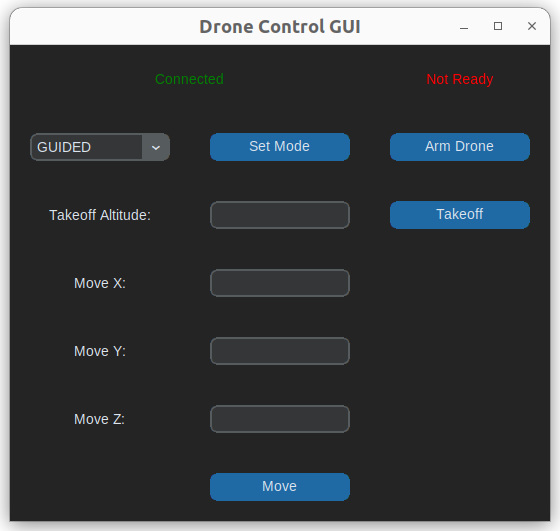
The simulation includes a simple GUI for sending position commands to individual drones:
GPS-referenced waypoints can also be planned via QGroundControl:

Namespacing in ArduPilot
ArduPilot’s namespacing uses the robot name directly (e.g., iris_1, iris_2). Each drone gets:
- Its own SITL instance with dedicated ports (master:
5760 + i*10, SITL:5501 + i*10) - System IDs assigned sequentially
- Fully scoped ROS 2 nodes: state publishers, bridges, sensor streams, and TF trees all under the vehicle namespace
Feeding in External Odometry
ArduPilot uses a different approach for external odometry compared to PX4. Instead of a custom message type, it expects transforms on the /ap/tf topic. The framework includes a relay node that bridges Gazebo TF data to ArduPilot:
gz/tf → tf (ROS) → ap/tf (ArduPilot)
The EKF3 parameters need to be configured to use vision as the position/velocity source:
AHRS_EKF_TYPE 3
EK3_SRC1_POSXY 6    # ExternalNav for XY position
EK3_SRC1_POSZ 1     # Barometer for Z
EK3_SRC1_VELXY 6    # ExternalNav for XY velocity
EK3_SRC1_VELZ 6     # ExternalNav for Z velocity
EK3_SRC1_YAW 6      # ExternalNav for yaw
VISO_TYPE 1          # Enable visual odometry
For more details, see the ArduPilot Cartographer SLAM guide and the multiagent DDS support PR that enabled this for multiple vehicles.
Custom Worlds
Both frameworks share the same set of simulation worlds, including realistic photogrammetry-based environments:
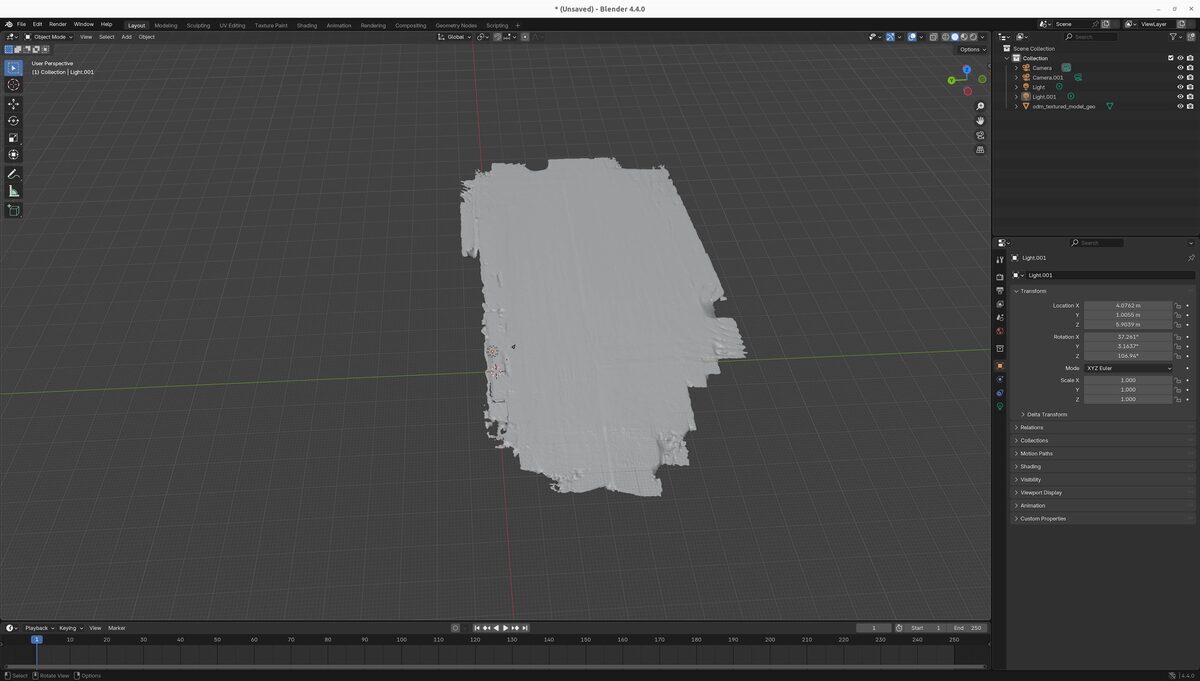
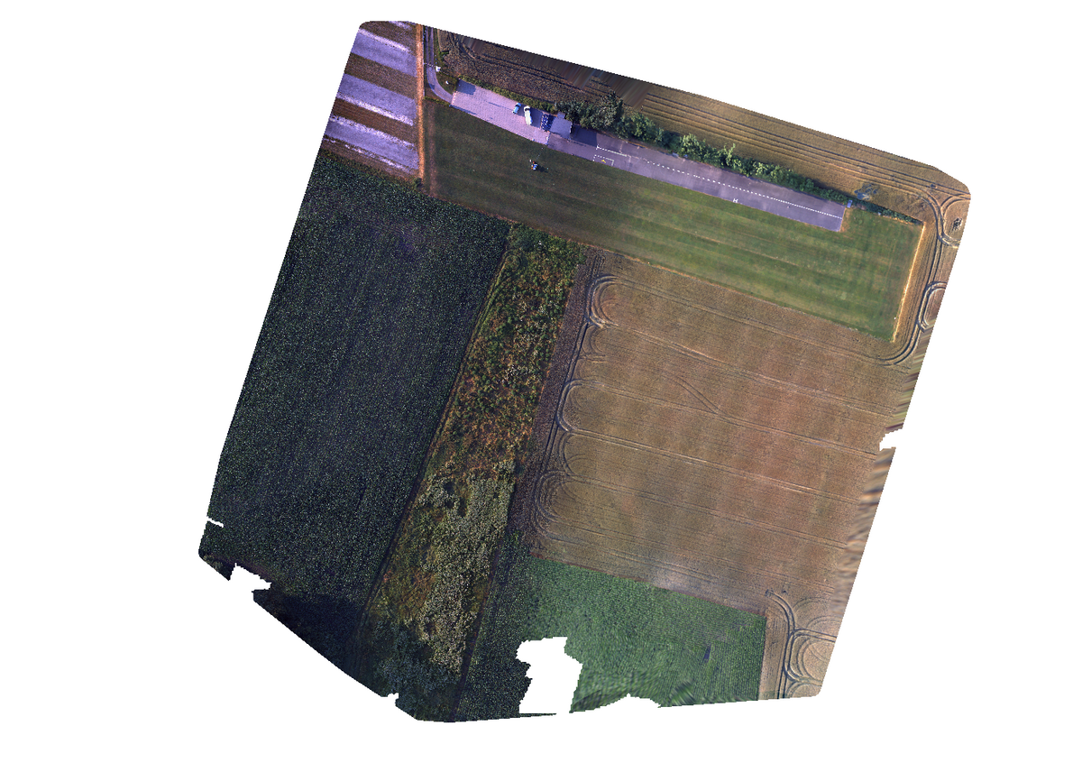
The modelflughafen world was created from drone photogrammetry data processed through OpenDroneMap and imported into Gazebo, providing a realistic outdoor testing environment.
PX4 vs ArduPilot: Key Differences
| Aspect | PX4 | ArduPilot |
|---|---|---|
| Namespace pattern | px4_<i> | Robot name (e.g., iris_1) |
| External odometry input | VehicleOdometry message on uORB | TF transforms via /ap/tf |
| Coordinate frame | FRD (Front-Right-Down) | ENU (East-North-Up) via ROS |
| Sensor config | Xacro macros | Xacro macros |
| Port allocation | 14540 + i*10 | 5760 + i*10 |
| Ground robots | Supported | Supported (Wild Thumper, Mecanum) |
| Fixed-wing | Supported | Supported |
Getting Started
If you want to try it out:
- PX4: github.com/TannerGilbert/PX4-Multiagent-Simulation
- ArduPilot: github.com/aau-cns/Ardupilot_Multiagent_Simulation
- ArduPilot base package: github.com/ArduPilot/ardupilot_gz
Both repositories include detailed READMEs with full installation instructions and are actively maintained. Contributions and issues are welcome.